What is Hyperspectral Imaging?
Hyperspectral imaging is a non-destructive technique that explores the electromagnetic spectrum far beyond the red, green, and blue (RGB) bands that are detected by standard colour cameras. This method can image over a wide range of bands stretching from the visible to the near-infrared.

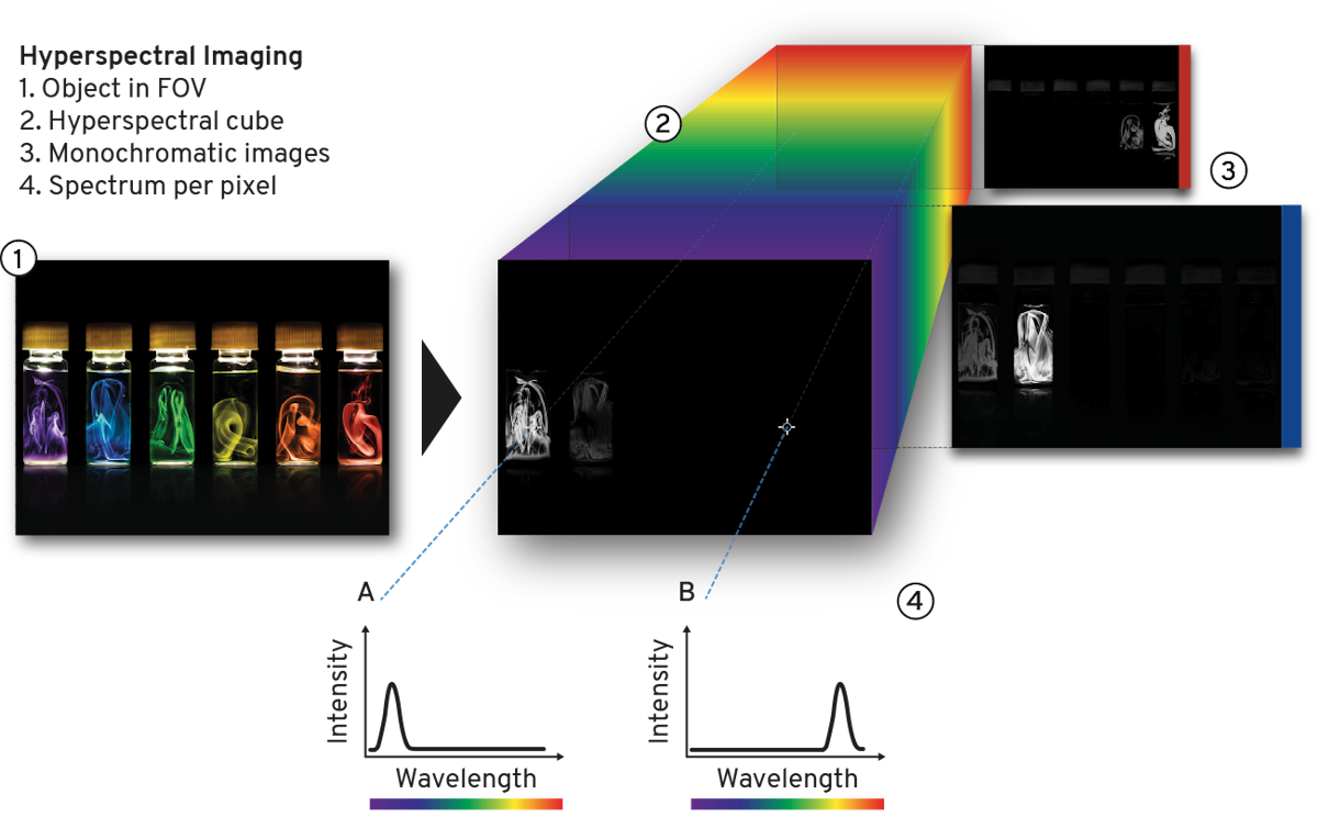
Hyperspectral imaging acquires narrow (< 10 nm) and contiguous wavelength bands and provides the spectrum of each pixel. By comparison, multispectral imaging acquires a number of discrete bands and does not reconstruct the spectrum. Photon etc. provides Bragg filters for two levels of band resolution: 2 to 5 nm and less than 1 nm.
Careful analysis of the spectral and spatial information found in the image’s pixels can help differentiate between the spectral signatures of a sample’s subcomponents. For example, the material or tissue analyzed can be mapped according to its molecular content.
Hyperspectral Data Cube
The stack of monochromatic images that a sample generates, each a subset of its spatial and spectral information, represents its hyperspectral data cube. With one spectrum per pixel, the larger the sensor, the richer the data set, which can number above a million. This can be processed by Photon etc.’s proprietary software, PHySpec, as well as other third-party software such as ImageJ or MATLAB.
Global Imaging versus Raster Scanning
Hyperspectral global imaging acquires monochromatic images and scans the wavelengths. In contrast, a spectral measurement performed with raster scanning technology is taken point by point or line by line by moving the sample, the sensor, or the excitation source. The number of acquisitions being much lower in global imaging (a few hundred wavelengths compared to several hundreds of thousands of points in scanning), the excitation density can be reduced while maintaining short measurement acquisition times. Global imaging therefore does not damage the sample, in addition to offering high spectral (~ nm) and spatial (~ µm) resolution. Also, since the whole field of view is imaged simultaneously, moving object trajectories can be reconstructed.
Photon etc.’s Global Imaging Technology
This video shows the conceptual difference between hyperspectral global imaging and raster scan (line scan, pushbroom). With global imaging, only a few monochromatic images are required to obtain a hyperspectral cube of data (X-Y spatial, Z spectral). With raster scan technologies, a spectrum needs to be acquired on each point/line within the desired field of view.
What is a Volume Bragg Grating?
A volume Bragg grating (VBG) is a diffraction grating in which there is a periodic modulation of the refractive index through the entire volume of a photosensitive material. This modulation can be oriented either to transmit (Fig. 3) or reflect (Fig. 4) the incident beam. VBGs can be fully described by the following parameters (ref. Fig. 3): the thickness of the grating, the refractive index of the photo-thermo-refractive glass (n0), the period (⋀) of the grating (or spatial frequency f = 1/⋀), the angle (θ) between the incident beam and the normal of the entrance surface (N), and the inclination of the Bragg planes (φ) defined as the angle between the normal (N) and the grating vector (Kg).

Only a small fraction of the incident beam respects Bragg’s law and will be diffracted. In order to select which wavelength will be diffracted, the angle of the filter is adjusted to meet Bragg’s condition: λB = 2n0Λcos(θ + φ), where λB is the diffracted wavelength. As shown in Fig. 3, for transmission gratings, φ = π/2 (Bragg planes are perpendicular to the entrance surface). In this case, the Bragg condition becomes λB = 2n0Λsin(θ).
As mentioned, this condition is valid for transmission gratings and has to be altered for reflection gratings where Bragg planes are parallel to the entrance surface (ref. Fig. 4). For reflection gratings, φ = 0 and the Bragg condition becomes λB = 2n0Λcos(θ). Wavelengths that do meet Bragg’s condition pass through the filter undiffracted.

Bragg Tunable Filter
A Bragg tunable filter is a filter that exploits Bragg gratings in order to extract a small bandwidth of wavelengths out of a polychromatic input. As stated by Bragg’s law, θ determines which wavelength is diffracted. Hence, by tuning the angle of the grating, it is possible to scan the output wavelength over hundreds of nanometers. This technology allows for the detection of a whole image at a specific wavelength band.
Our Products

L-EOS™
L-EOS is an infrared push broom hyperspectral imager scanning from 0.9 to 2.5 µm.

LLTF CONTRAST™
The LLTF CONTRAST is a non-dispersive tunable (400-2500 nm) bandpass filter based on volume Bragg gratings.

S-EOS™
S-EOS is a global hyperspectral camera continuously tunable from 900 to 1620 nm or from 900 to 2500 nm.

HyperCube™
The HyperCube is a hyperspectral filter continuously tunable in the VIS, NIR and SWIR spectral ranges.